Login
Remember
Register
Home
All Activity
Q&A
Questions
Hot!
Unanswered
Tags
Categories
Users
Ask a Question
Ask a Question
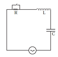
In the LCR circuit shown in Fig , the ac driving voltage is `v = V_m sin ωt`. Describe subsequent motion of
0
votes
asked
Mar 20, 2022
in
12th Physics
by
varun
(
6.7k
points)
In the LCR circuit shown in Fig , the ac driving voltage is `v = V_m sin ωt`.
Describe subsequent motion of charges.
marks2
chapter7
#sub
Please
log in
or
register
to answer this question.
0
Answers
Categories
All categories
Maths
(8.6k)
Science
(14)
Physics
(3.4k)
11th Physics
(1.5k)
12th Physics
(1.9k)
Related questions
In the LCR circuit shown in Fig , the ac driving voltage is `v = V_m sin ωt`. Write down the equation of motion for q
In the LCR circuit shown in Fig , the ac driving voltage is `v = V_m sin ωt`. At t = t0, the voltage source stops and R is short circuited. Now write down how much energy is stored in each of L and
Consider the LCR circuit shown in Fig . Find the net current i and the phase of i. Show that ` I=Z/V` . Find the impedence Z for this
For an LCR series circuit, phasors of current i and applied voltage `V=V_0 sinomegat` are shown in diagram at `t =0`. Which of the following is/are
In an AC series L-C-R circuit, applied voltage is `V= {100sqrt2 sin (omegat + 45°)} V` Given that, `R - 30 Omega, X_L = 50 Omega and X_c = 10 Omega.` Now match the following two columns. Column I Column II A. Current in the circuit p. 120 SI units B. Power dissipated in the circuit q. 60 SI units C. Potential difference across resistance r. 2 SI units D. Potential difference across inductance s. None