In the circuit shown in figure `E=25V, L=2H, C=60 muF, R_1 = 5Omega and R_2=10Omega`. Switch S is closed at `t = 0.`
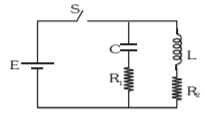
| Column-I | Column-II |
| (A) Current through `R_1` at t = 0 | (P) 0 |
| (B) Current through `R_2` at t = 0 | (Q) 5A |
| (C) Current through `R_1` at `t =oo` | (R) 2.5 A |
| (D) Current through `R_2` at `t =oo` | (S) 7.5 A |
| | (T) None of these |