Login
Remember
Register
Home
All Activity
Q&A
Questions
Hot!
Unanswered
Tags
Categories
Users
Ask a Question
Ask a Question
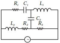
Draw the effective equivalent circuit of the circuit shown in Fig , at very high frequencies and find the effective
0
votes
asked
Mar 20, 2022
in
12th Physics
by
varun
(
6.7k
points)
Draw the effective equivalent circuit of the circuit shown in Fig , at very high frequencies and find the effective impedance.
marks2
chapter7
#sub
Please
log in
or
register
to answer this question.
0
Answers
Categories
All categories
Maths
(8.6k)
Science
(14)
Physics
(3.4k)
11th Physics
(1.5k)
12th Physics
(1.9k)
Related questions
How does the sign of the phase angle φ, by which the supply voltage leads the current in an LCR series circuit, change as the supply frequency is gradually increased from very low to very high
In the LCR circuit shown in Fig , the ac driving voltage is `v = V_m sin ωt`. At t = t0, the voltage source stops and R is short circuited. Now write down how much energy is stored in each of L and
In series LCR circuit, the plot of `I_max VS ω` is shown in Fig . Find the bandwidth and mark in the
Consider the LCR circuit shown in Fig . Find the net current i and the phase of i. Show that ` I=Z/V` . Find the impedence Z for this
In a L–C circuit parallel combination of inductance of 0.01 H and a capacitor of `1muF` is connected to a variable frequency alternating current source as shown in figure. Draw a rough sketch of the current variation as the frequency is changed from 1kHz to